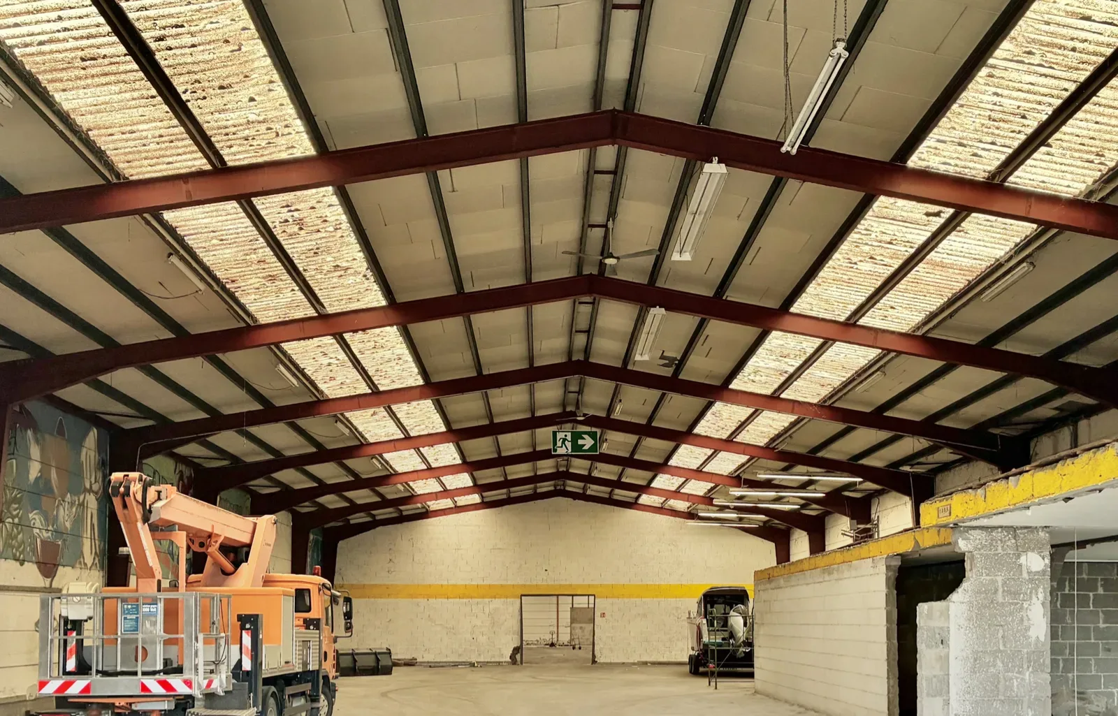
Location and building documents are provided after a short qualification.
Current status: The original structural calculation has been requested from the building records archive. Plate thicknesses, steel grade and design loads will be added once received. This article reflects what is documented today from the building file, photographs and a site visit; estimated values are marked “approx.”.
TRS1500CSWBS01Identification
- Object ID
- TRS1500CSWBS01
- Long form
- TRS-1500-CSWBS-W20L75-01
- Description
- clear-span steel hall structure, pitched roof
- Passport no.
- HP-20261026-01
- Location
- Rhineland-Palatinate, Germany; exact site after qualification
Origin and documents
- Built
- before 1990, exact year open
- Building file
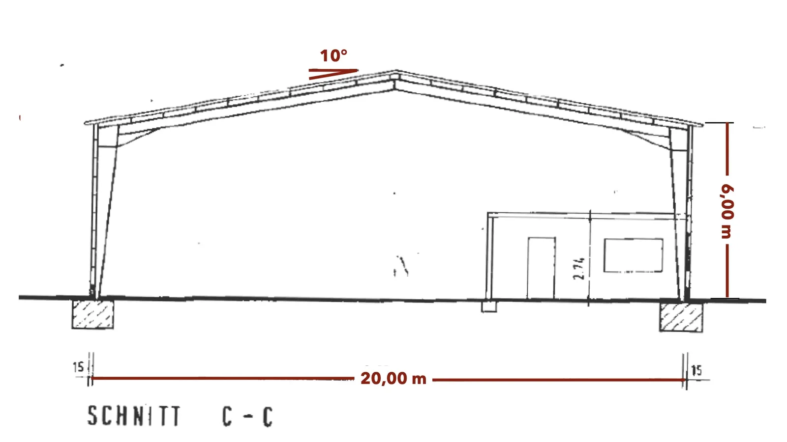
- building description, area calculation, section C-C
- Structural calculation
- requested from the records archive
- Photos
- existing condition and details, October 2026
Geometry
- System dimension
- 20.00 × 75.00 m (basis of the object ID)
- External width (existing)
- 20.30 m incl. wall
- Grid
- 12 bays × 6.25 m, axes 1–13
- Eaves / ridge
- 6.00 m / approx. 7.76 m
- Roof pitch
- 10°, duo-pitch
Structure
- Columns
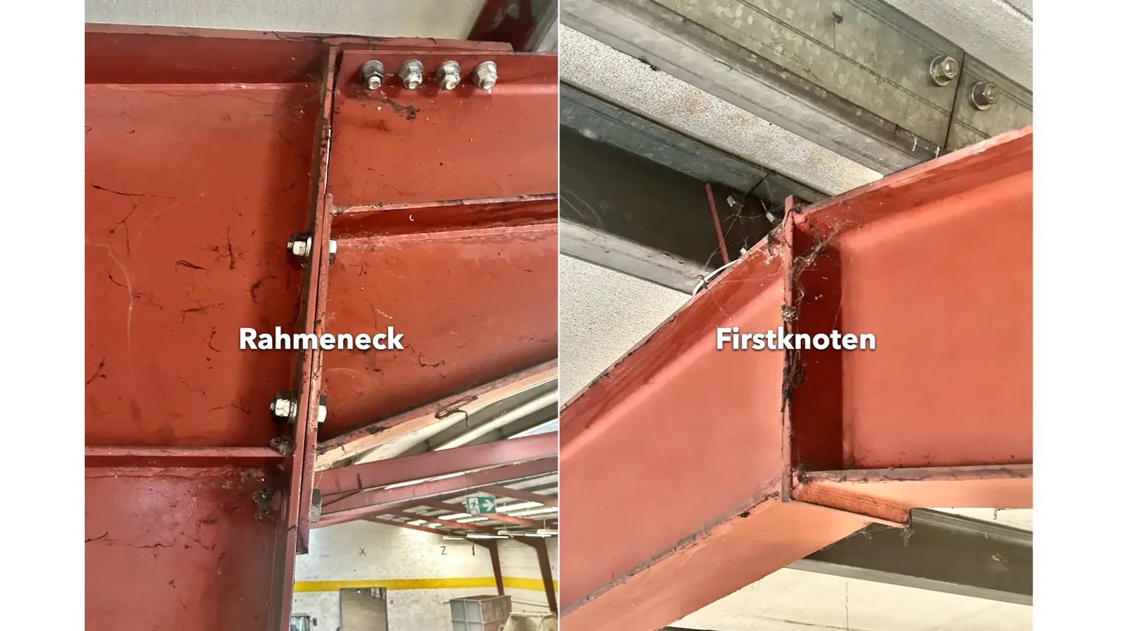
- tapered welded plate sections
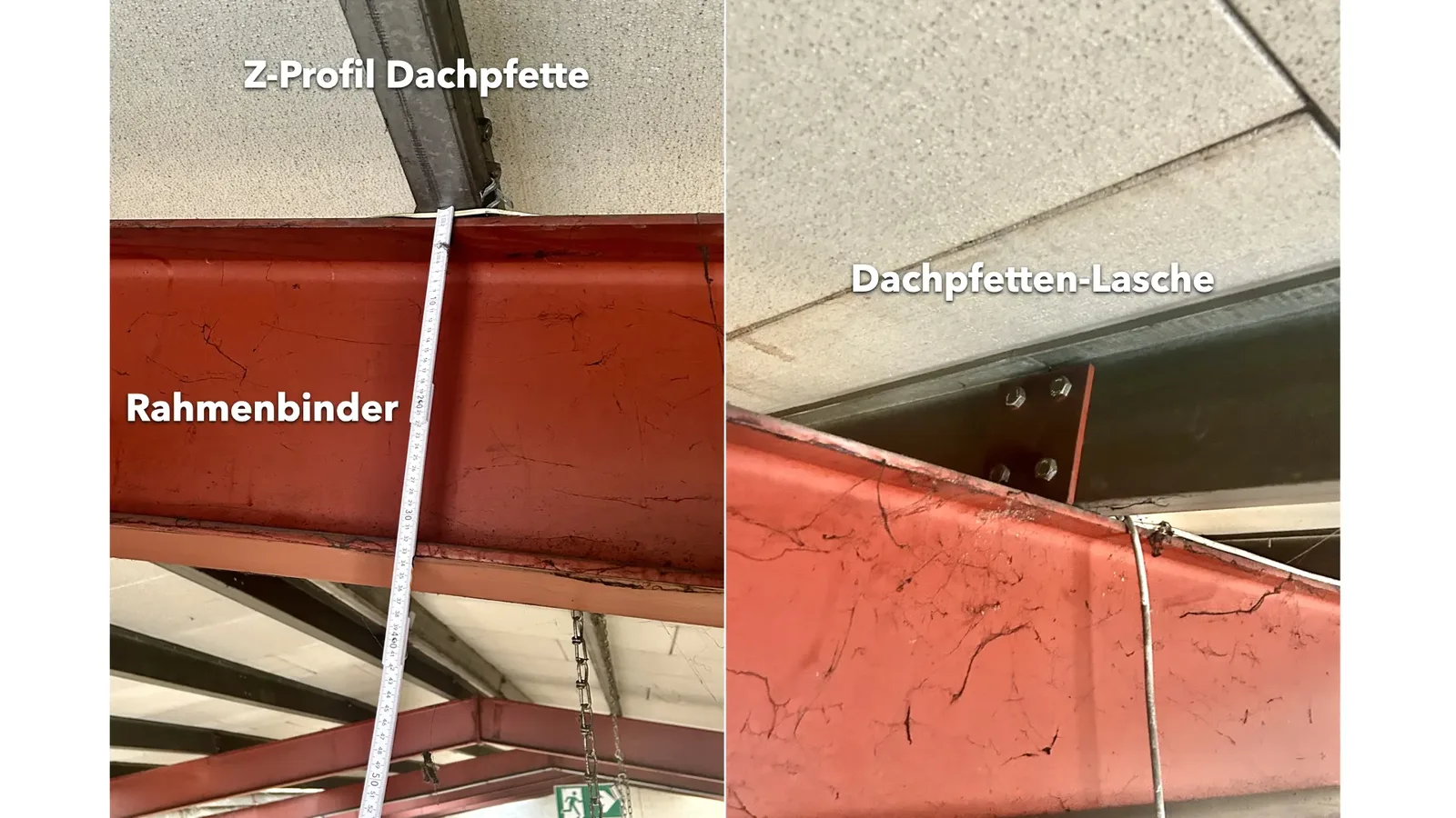
- Rafters
- welded, haunched at the eaves
- Eaves connection
- bolted
- Apex
- welded, single apex plate, no haunch
- Column base
- base plate with anchor bolts (to be confirmed)
Secondary structure and gable
- Purlins per roof slope
- 1 eaves purlin (C) + 9 Z-purlins, galvanised
- Roof bracing
- all 12 bays, both sides in the eaves strip
- Side rails
- none (aerated concrete panels span axis to axis)
- Gable axis 1
- 4 gable posts, central roller door, door header
- Canopy axis 1
- mono-pitch, 6 galvanised cantilever arms, 4 purlins
Terms
- Price
- on request after qualification
- Availability
- dismantling from week 48/2026
- Scope
- steel structure ex site
- Not included
- roof covering, aerated concrete walls, foundations
- Dismantling
- by the buyer or via our partner network
Thirteen welded portal frames for a 20 m clear span
The portal frames are economically welded from steel plate. The columns are tapered: narrow at the base plate, wide at the bolted eaves connection. The rafters are haunched at the eaves and welded together at the ridge via a single apex plate, so each rafter is one continuous member from eaves to eaves. Current photos show no visible rust on the eaves bolts – a good basis for careful dismantling.
- Clear span: 20 m free span for machinery, storage, a riding arena or handling.
- Usable height: 6.00 m to the eaves, ridge approx. 7.76 m at a 10° pitch.
- Complete roof secondary structure: one eaves purlin and nine Z-purlins per roof slope, roof bracing in all twelve bays.
TRS drawings
The information drawings are our own redrawings based on the building file and photographs. Dimensions in m; ridge height and the gable and canopy dimensions are derived or estimated.
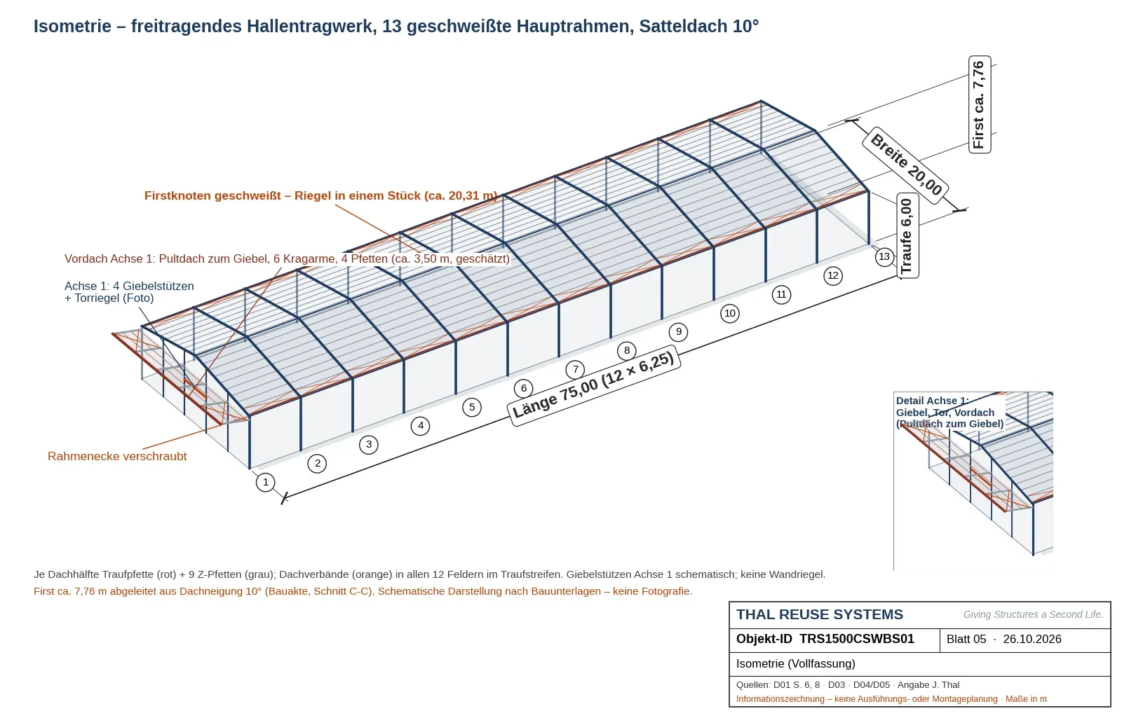
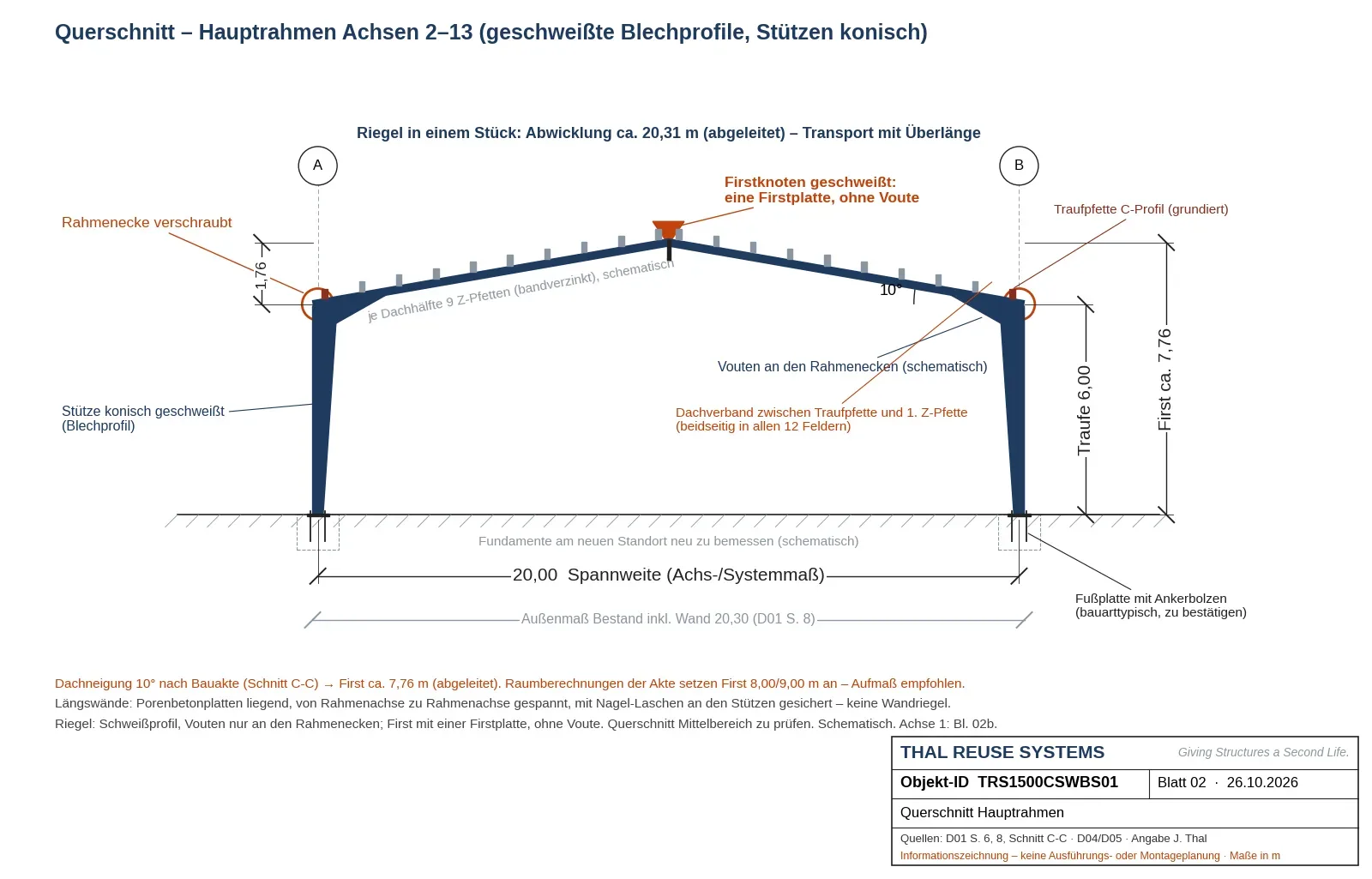
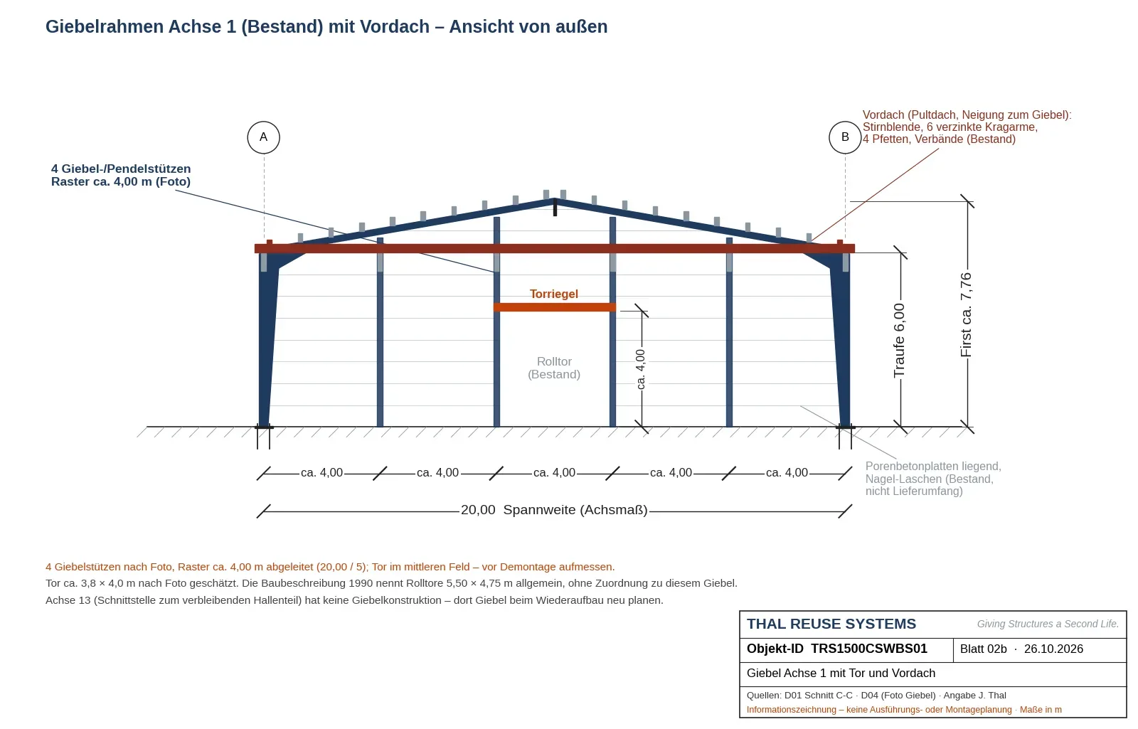
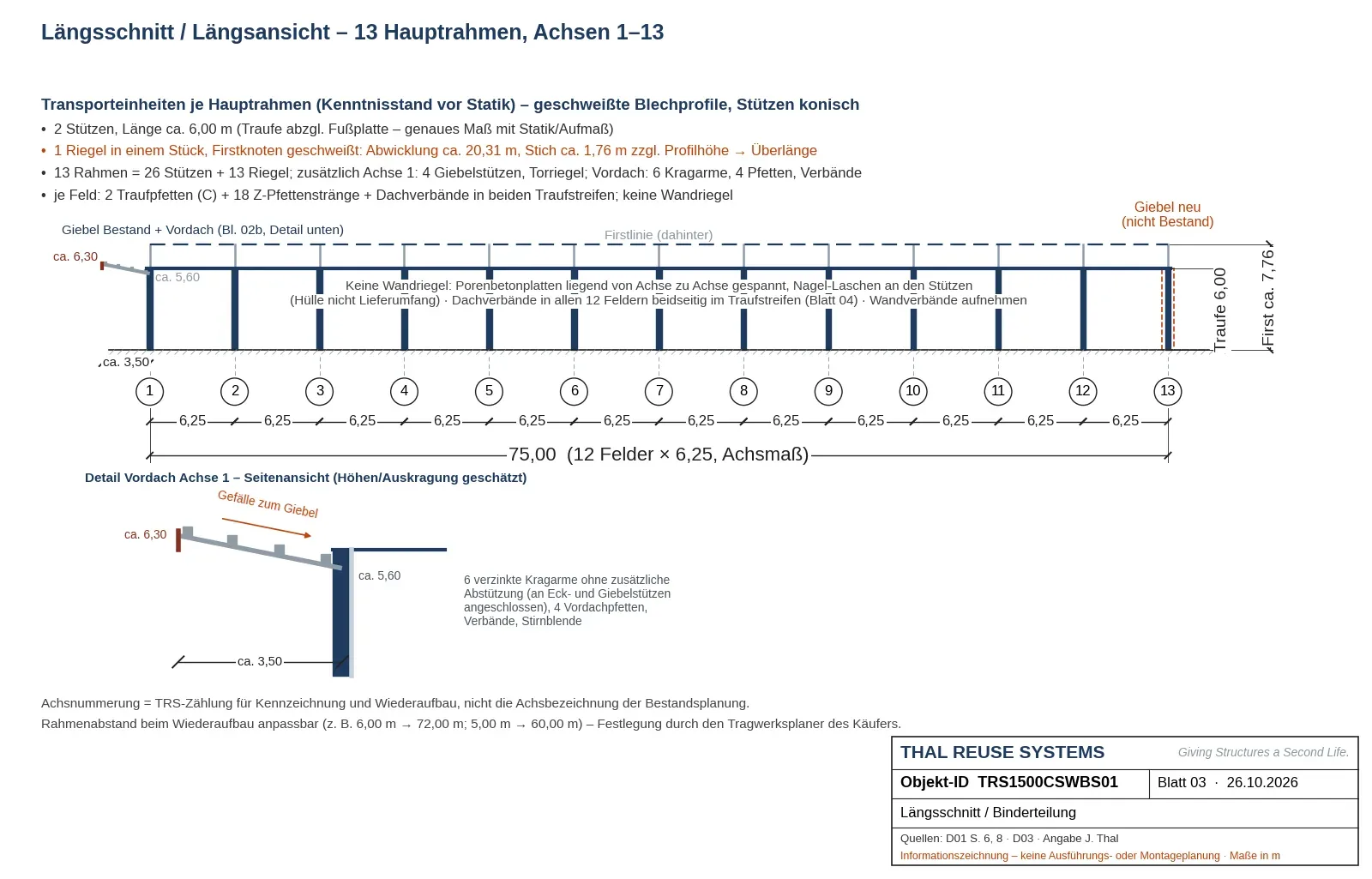
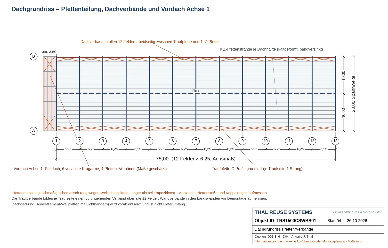
Purlin spacing, bracing layout and the gable and canopy dimensions are schematic or derived from photos; a site survey and the requested structural calculation are authoritative.
Detail photos
Logistics: rafters in one piece
Because the apex is welded, each rafter is loaded as one piece: developed length approx. 20.31 m, rise at the ridge approx. 1.76 m plus section depth. This will probably require an abnormal-load permit for overlength and a crane for loading. Each frame adds two columns of approx. 6 m; each bay adds two eaves purlins and 18 Z-purlin runs. Exact lengths and weights will follow from the survey and structural calculation.
Frame spacing adjustable on re-erection
The 75 m apply to the original 6.25 m bay spacing. For sites with higher snow or wind loads the structural engineer can specify closer frame spacing; the hall then becomes shorter.
| Frame spacing | Bays | Hall length (grid) |
|---|---|---|
| 6.25 m | 12 | 75.00 m |
| 6.00 m | 12 | 72.00 m |
| 5.50 m | 12 | 66.00 m |
| 5.00 m | 12 | 60.00 m |
| 4.50 m | 12 | 54.00 m |
Geometry only, not a structural verification. Purlins, bracing and cladding substructure must be redesigned if the spacing changes.
Design loads and range of use
The design loads of the original calculation are not yet available. We will add a Eurocode classification for snow, wind and seismic zones once the calculation is received. Typical strengthening options for welded frames are closer frame spacing, additional or stronger purlins and bracing, fly braces to the rafter inner flange, welded-on plates at eaves and rafters, a tie between the eaves or a lower eaves height.
The information on range of use and strengthening options is an indicative assessment based on the available documents. It does not replace a structural calculation. THAL REUSE SYSTEMS gives no warranty for it. Suitability for a specific site and the type and extent of any strengthening must be verified by a structural engineer appointed by the buyer.
Scope of supply and additions
- Included: 13 portal frames, purlins, roof bracing, gable posts and door header of axis 1, canopy with cantilever arms.
- Not included: the asbestos-containing roof covering (professionally removed before dismantling), the aerated concrete walls and the foundations.
- To be designed new: the gable at the second end, side rails for new trapezoidal or sandwich-panel cladding, and foundations at the new site.
Possible uses
- machinery and equipment shed
- agricultural store, timber and forestry shed
- exercise or riding arena
- workshop and operations hall
- warehouse and handling hall for trade and smaller hauliers
Dismantling and re-erection
- Survey: measured survey, marking of members by axis, check of connections.
- Hazardous materials: professional removal of the roof covering by the owner before the structure is dismantled.
- Dismantling: purlins, bracing and frames in reverse order of erection via our partner network.
- Transport: rafters in one piece with overlength, columns and secondary members by component group.
- Re-erection: design by the buyer’s architect, structural engineer and hall builder; new foundations and cladding at the new site.
Frequently asked questions
What does the structure cost? We quote the price on request after a short qualification. It applies to the steel structure ex site.
When can it be dismantled? From week 48/2026. Until then the owner removes the roof covering; an inspection in place is possible beforehand.
Can I build the hall shorter? Yes. Fewer bays or closer spacing give a shorter hall. Gable, bracing and cladding are then redesigned.
Is there a structural calculation? The original calculation has been requested from the records archive. A new structural verification to Eurocode is always required for the new site.
Request documents
After qualification you receive the location, hall passport, drawings and building documents. Please quote object ID TRS1500CSWBS01.
Johann Thal · Founder THAL REUSE SYSTEMS
Phone +49 30 80584249 · sales@thalreuse.systems · thalreuse.systems
Want to sell a hall? Talk to us – we buy or find the right buyer through our network. Offer a hall →
All information is based on the building file, photographs and a site visit, without warranty; dimensions are approximate. Subject to prior sale. This article does not replace professional design, structural or permit review at the new site.
Photos and drawings: © THAL REUSE SYSTEMS