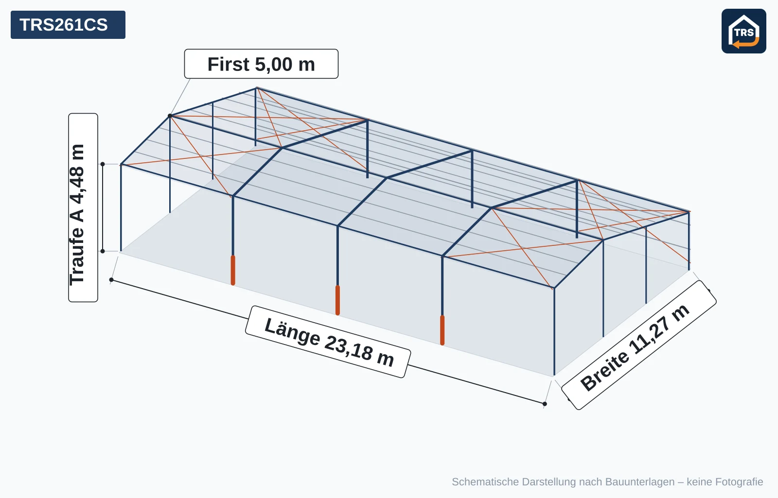
Location, full building documents and – where available – current photos are provided after a short qualification and signature of the THAL REUSE STANDARD Fair Use Agreement (TRS-FA).
TRS261CSIdentification
- Object ID
- TRS261CS
- Long form
- TRS-261-CS-W11L23-01
- Construction
- steel frame hall, one-off design
- Description
- open-sided shelter, asymmetric duo-pitch roof
- Hall passport no.
- HP-20261108-01
- Location
- exact location after qualification
Origin and documents
- Erected
- 1997
- Structural calc.
- 1996, 42 pages, DIN 18800 (partial safety factors)
- Check
- report of the checking engineer 1997: no objections
- Acceptance
- inspection without defects; final acceptance 1998
- Drawings
- shop drawings frames, gables, foundations, erection; parts list
Geometry
- Grid dimension
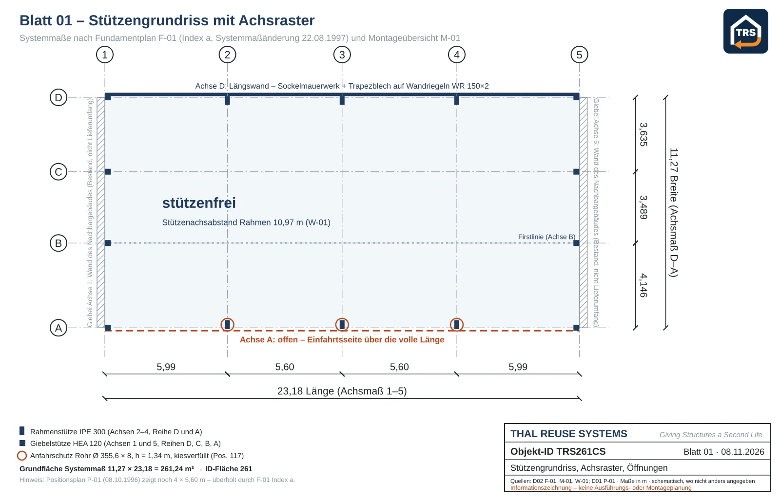
- 11.27 × 23.18 m (basis of object ID)
- Bays
- 4 bays: 5.99 / 5.60 / 5.60 / 5.99 m
- Eaves / ridge
- 4.48 m open side · 2.96 m rear wall · ridge 5.00 m
- Roof pitch
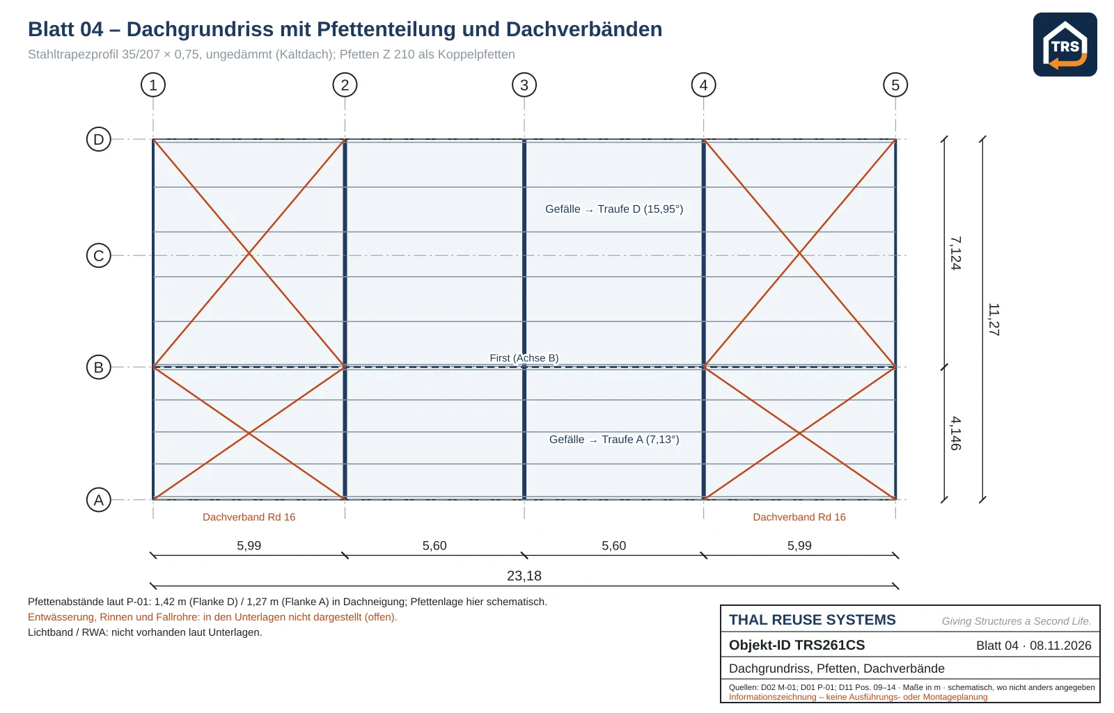
- 15.95° / 7.13°, asymmetric duo-pitch
- Clear height
- approx. 4.06 m below haunch, open side; survey to follow
Structure
- Frames
- 3 two-hinged frames IPE 300, haunched, clear span
- Gable frames
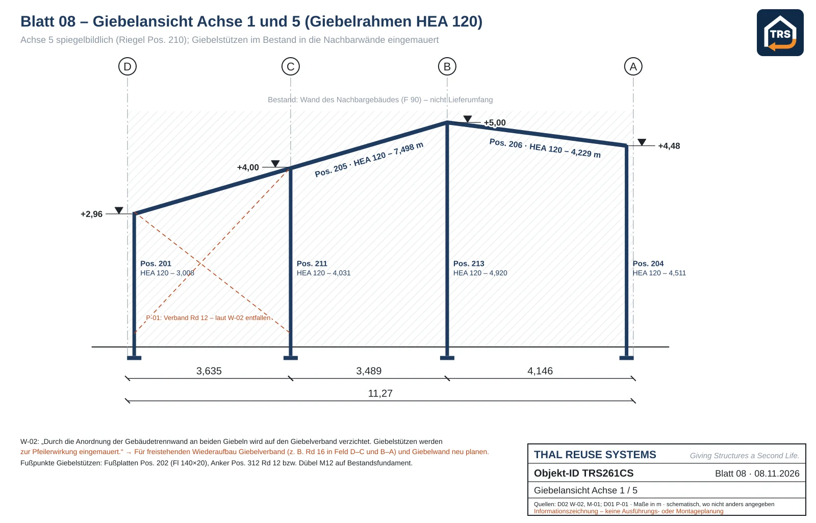
- HEA 120 in axes 1 and 5
- Purlins
- Z 210 × 2, coupled
- Bracing
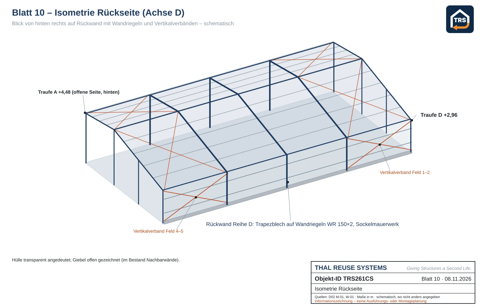
- roof bracing end bays, wall bracing rear wall
- Steel
- St 37-2 (S235), blasted and primed, approx. 8.5 t
- Connections
- rafter splices bolted HV-M20, ridge welded
Envelope and equipment
- Roof
- trapezoidal steel sheet 35/207 × 0.75 mm, uninsulated
- Rear wall
- trapezoidal sheet on side rails
- Long side
- open, impact protection at the columns
- Gables
- existing neighbouring walls – not included
- Doors / rooflights
- none
Terms
- Price
- on request after qualification
- Availability
- by arrangement
- Scope
- steel structure and cladding ex site
- Not included
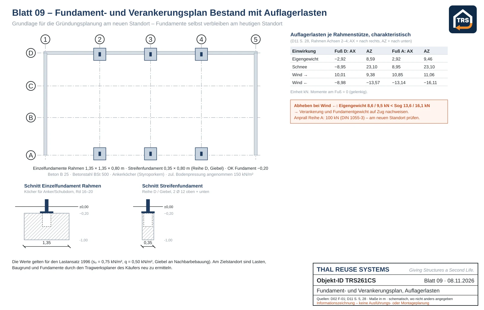
- foundations, plinth masonry, gable walls, foundations at new site
- Dismantling
- by buyer or via our partner network
Open shelter with rolled-section frames
The hall was designed as a shelter for agricultural machinery and placed between two existing buildings. Three two-hinged IPE 300 frames carry the asymmetric duo-pitch roof: 15.95° towards the closed rear wall with 2.96 m eaves, 7.13° towards the open entrance side with 4.48 m eaves.
- Clear span: 11.27 m free span for tractors, trailers and harvesters.
- Open: drive in along the full 23.18 m length without manoeuvring.
- Dismountable: three shipping pieces per frame, bolted with HV-M20; coupled purlins release bay by bay.
Dimensions on all reference levels
The object ID is derived from the grid dimension. For plot and foundations, the column centre distance and the heights also matter.
| Reference | Value | Note |
|---|---|---|
| Grid dimension (system) | 11.27 × 23.18 m | 261 m², basis of the object ID |
| Column centre distance | 10.97 m | frame columns rows D and A |
| Eaves / ridge | 2.96 / 4.48 / 5.00 m | rear wall / open side / ridge |
| Clear height | approx. 4.06 / 2.76 m | below haunch open side / rear wall, to be surveyed |
| Largest shipping piece | approx. 9.9 m | rafter, welded at ridge; standard trailer |
Structure: three IPE 300 frames
Each frame consists of three shipping pieces: two columns with welded haunches and one rafter welded at the ridge. The splices at the haunch ends are connected with end plates and four HV-M20 bolts each. The column bases are pinned; the Z 210 purlins are coupled. Roof bracing in the end bays and wall bracing in the rear wall stabilise the hall longitudinally. The drawings are labelled in German.
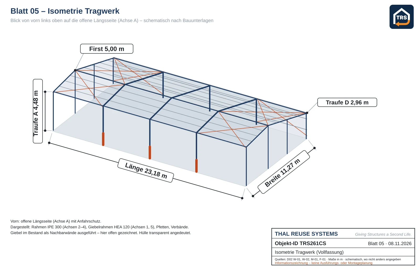
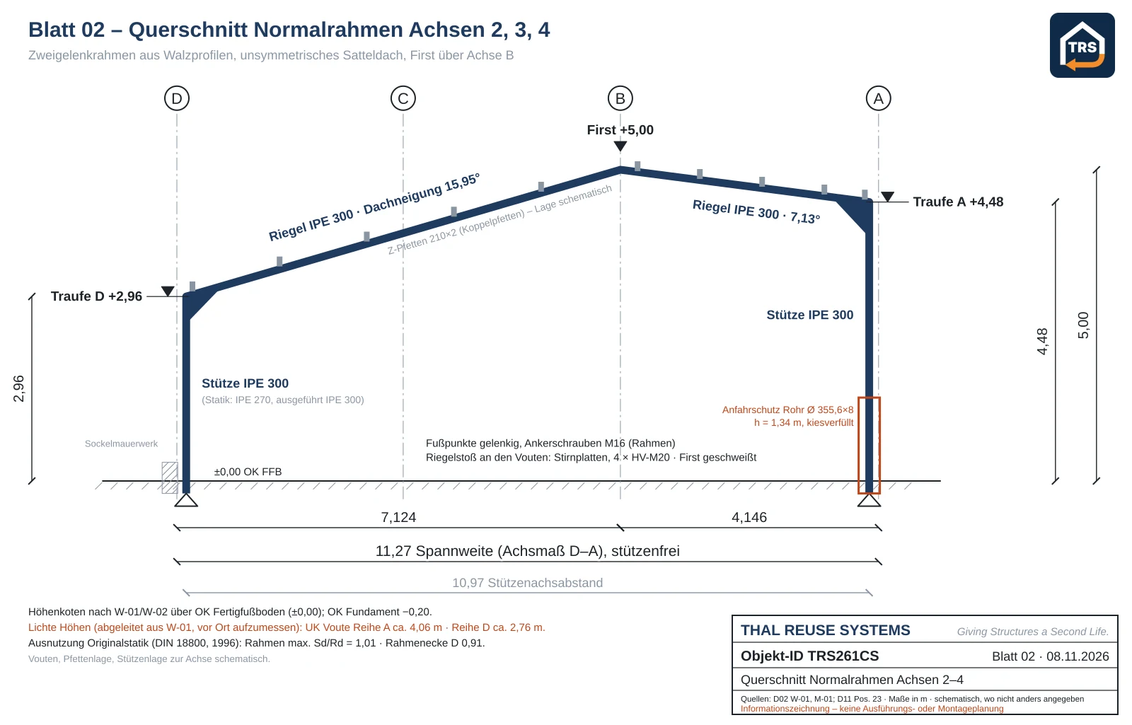
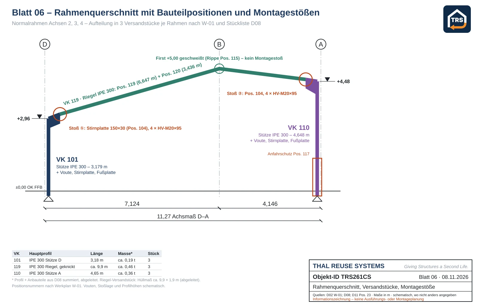
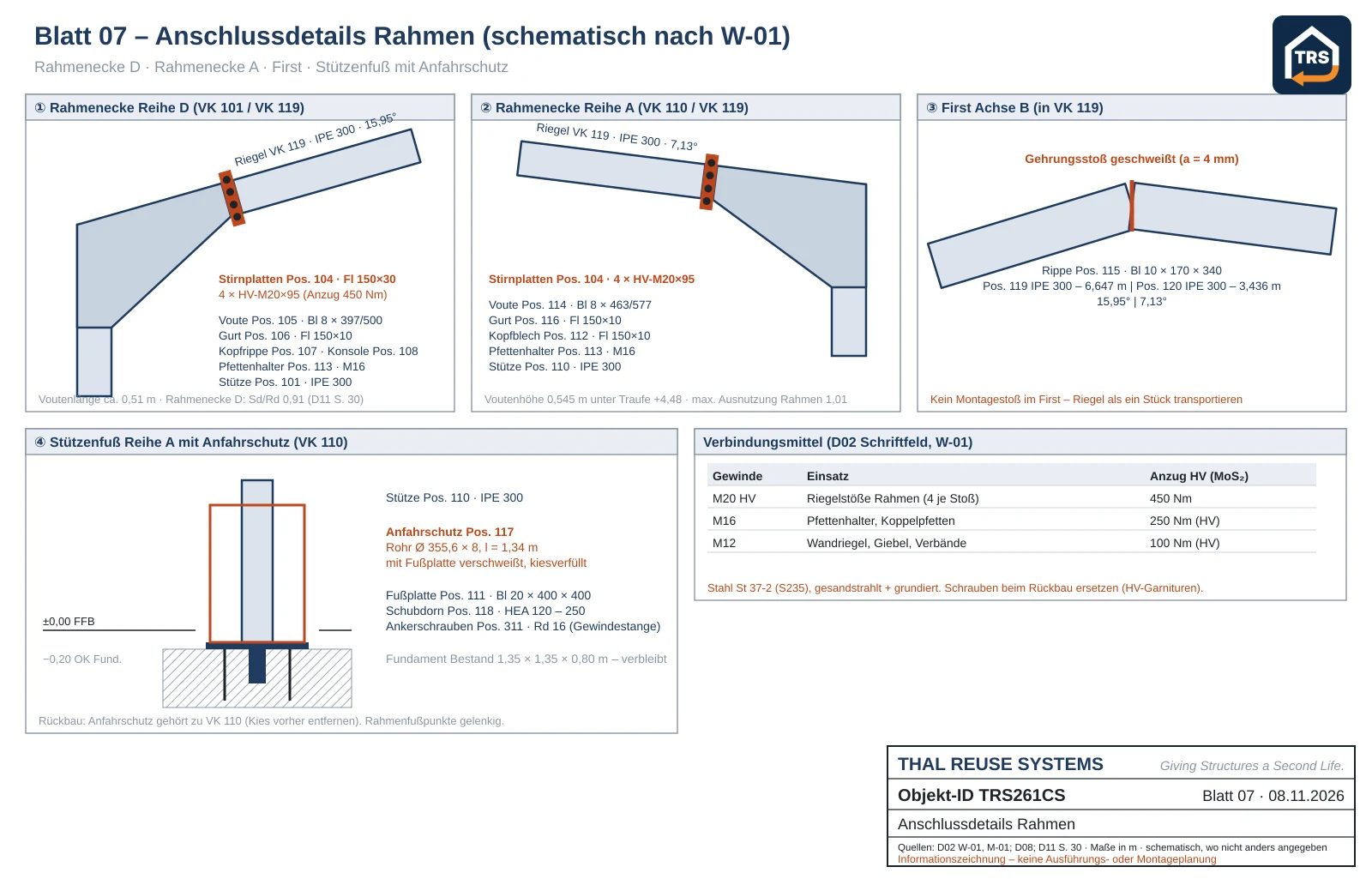
Plan, elevations and roof
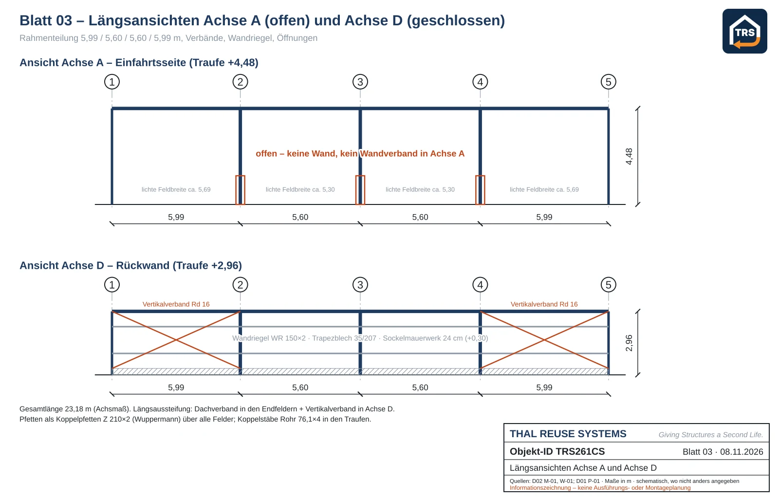
Gables, foundations and rear view
In the existing situation the gable columns are built into the walls of the neighbouring buildings; the hall has no gable bracing of its own. It therefore suits best as an extension to an existing building or as an infill between two buildings. For free-standing re-erection, gable bracing and gable walls must be added. Sheet 09 shows the support reactions of the original calculation as a basis for the new foundations.
Range of application under the Eurocodes (indicative)
The original calculation assumes 0.75 kN/m² snow and 0.50 kN/m² wind pressure; the frame is fully utilised. Transferred to DIN EN 1991-1-3/NA and DIN EN 1991-1-4/NA (Germany), this gives:
| Action | Zone | Limit | Classification |
|---|---|---|---|
| Snow | zone 1 | up to approx. 545 m a.s.l. | probably without strengthening |
| Snow | zone 1a | up to approx. 455 m a.s.l. | probably without strengthening |
| Snow | zone 2 | up to approx. 315 m a.s.l. | probably without strengthening |
| Snow | zone 2a, 3, North German lowlands | – | probably with strengthening |
| Wind | WZ 1 inland | 0.50 kN/m² | probably without strengthening (borderline) |
| Wind | WZ 2–3 inland | 0.65–0.80 kN/m² | probably with strengthening |
| Wind | coast, WZ 4, islands | ≥ 0.85 kN/m² | not recommended |
The information on the range of application and on possible strengthening measures is an indicative assessment based on the available documents. It does not replace a structural calculation. THAL REUSE SYSTEMS accepts no liability for it. Suitability for a specific site and the type and extent of any strengthening must be verified by a structural engineer appointed by the buyer.
Suitable second uses
Machinery and equipment shelter for agriculture, forestry, landscaping or municipalities; vehicle and trailer shelter; covered storage for timber, building materials or bales; extension to an existing hall or barn. With doors on the open side it becomes a compact storage or workshop hall.
Dismantling and re-erection
- Dismantling: remove cladding, release purlins bay by bay, separate frames at the HV splices.
- Marking: mark components with the position numbers of the shop drawings.
- Loading: rafter approx. 9.9 m, columns 3.2 and 4.7 m – standard trailer.
- Re-erection: new foundations designed for the new site, new HV bolt sets, add gables.
For the building permit at the new site we hand over the calculation, check report, shop drawings and parts list. On request our partner network handles dismantling, marking and loading.
Frequently asked questions
What does the hall cost? We quote the price on request after a short qualification.
When is the hall available? Availability is agreed with you – dismantling and collection by arrangement.
Is there a structural calculation? Yes. The 1996 calculation, the checking engineer’s report, shop drawings and the final acceptance are available.
Can the hall stand on its own? Yes, with additions: for free-standing re-erection, gable bracing and gable walls must be designed. Without them it suits an extension or infill.
Request documents
After qualification you receive location, exposé, hall passport and building documents. Please quote object ID TRS261CS.
Johann Thal · Founder THAL REUSE SYSTEMS
Phone +49 30 80584249 · sales@thalreuse.systems · thalreuse.systems
Would you like to sell a hall? Talk to us – we buy or find the right buyer through our network. Offer a hall →
All details are based on the building documents and are given without warranty; dimensions are approximate. Subject to prior sale. This article does not replace design, structural or permit checks at the new site.
Drawings: © THAL REUSE SYSTEMS